Vibrodiagnostics of a steam turbine
Content: Вибродиагностика паровой турбины.rar (298.23 KB)
Uploaded: 07.06.2022
Positive responses: 0
Negative responses: 0
Sold: 0
Refunds: 0
$3.58
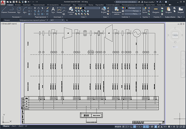
Working draft of vibration diagnostics of a steam turbine at a thermal power plant.
Project of monitoring, control and diagnostics system for turbine unit PT-65-130/13.
The system has three levels of hierarchy. The lower level is sensors and actuators, the middle one is IT-14 system modules, the upper one is a data collection and processing server and an operator station.
Communication between the upper and middle levels is carried out via the CAN line. The signals involved in the protections, from the measuring modules to the protection modules, are carried out via dedicated lines.
The composition of the vibration diagnostics system.
The composition of the equipment of the first level:
• channel for measuring the vibration of bearing housings - 18 channels;
• shaft rotation speed measurement channel - 1 channel;
• channel for measuring the relative expansion of the rotor (ORR) - 2 channels;
• rotor displacement measurement channel (OSR) - 3 channels;
• channel for measuring rotor curvature (IR) - 1 channel;
• channel for measuring the thermal expansion of the body (TRK) - 2 channels.
Composition of the transducer level:
• vibration transducers - 18 pieces;
• rotation speed converter (tachometric) - 1 piece;
• OSR converter - 3 pieces;
• transducer IR - 1 piece;
• fuel dispenser converter - 2 pcs.;
• current measurement module (0-5mA) - 1 piece;
• relay module - 4 pcs.;
• protection module - 4 pcs.;
• indicator - 1 pc.
Upper level:
• data collection server - 1 piece;
• Operator workstation - 1 pc.
Format - DWG compatible with AutoCAD 2004-2017, Compass, ZWCAD, nanoCAD, BricsCAD, etc.
No feedback yet