Solution K2-66 (Figure K2.6 condition 6 SM Targ 1988)
Content: k2-66_1988.rar (23.97 KB)
Uploaded: 08.05.2016
Positive responses: 0
Negative responses: 0
Sold: 0
Refunds: 0
Seller: Михаил_Перович
information about the seller and its items
Loyalty discount! If the total amount of your purchases from the seller more than:
| $1 | the discount is | 1% |
| $5 | the discount is | 2% |
| $10 | the discount is | 3% |
| $20 | the discount is | 5% |
| $50 | the discount is | 7% |
| $100 | the discount is | 10% |
| $200 | the discount is | 15% |
$0.55
Solution K2-66 (Figure K2.6 condition 6 SM Targ 1988)
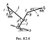
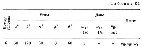
The flat mechanism consists of rods 1 - 4 and a slide B, connected with each other and with fixed supports O1 and O2 with hinges (Fig. K2.0-K2.9). The lengths of the rods are l1 = 0.4 m, l2 = 1.2 m, l3 = 1.4 m, l4 = 0.8 m. The position of the mechanism is determined by the angles α, β, γ, φ, θ, which together with other quantities are given in Table. K2. Point D in all figures and point K in Fig. K2.7-K2.9 in the middle of the corresponding rod. Determine the values indicated in the table in the "Find" column. Find also the acceleration aA of the point A of the rod 1, if the rod 1 has at the given time the angular acceleration ε1 = 10 s-2 Arc arrows in the figures show how the corresponding angles are to be plotted in the drawing; (for example, the angle γ in Figure 1 should be postponed from the rod DE against the clockwise direction, and in Figure 2 - from the rod AE in a clockwise direction). Draw a drawing from the rod, the direction of which is determined by the angle α; the slider B and its guides are shown for greater clarity, as in Example K2 (see Figure K2). The specified angular velocity is considered to be directed counterclockwise, and the specified speed vB is from point B to b.
The flat mechanism consists of rods 1 - 4 and a slide B, connected with each other and with fixed supports O1 and O2 with hinges (Fig. K2.0-K2.9). The lengths of the rods are l1 = 0.4 m, l2 = 1.2 m, l3 = 1.4 m, l4 = 0.8 m. The position of the mechanism is determined by the angles α, β, γ, φ, θ, which together with other quantities are given in Table. K2. Point D in all figures and point K in Fig. K2.7-K2.9 in the middle of the corresponding rod. Determine the values indicated in the table in the "Find" column. Find also the acceleration aA of the point A of the rod 1, if the rod 1 has at the given time the angular acceleration ε1 = 10 s-2 Arc arrows in the figures show how the corresponding angles are to be plotted in the drawing; (for example, the angle γ in Figure 1 should be postponed from the rod DE against the clockwise direction, and in Figure 2 - from the rod AE in a clockwise direction). Draw a drawing from the rod, the direction of which is determined by the angle α; the slider B and its guides are shown for greater clarity, as in Example K2 (see Figure K2). The specified angular velocity is considered to be directed counterclockwise, and the specified speed vB is from point B to b.
No feedback yet