Solution K3-24 (Figure K3.2 condition 4 SM Targ 1989)
Content: k3-24.doc.RAR (37.42 KB)
Uploaded: 26.04.2016
Positive responses: 0
Negative responses: 0
Sold: 0
Refunds: 0
Seller: Михаил_Перович
information about the seller and its items
Loyalty discount! If the total amount of your purchases from the seller more than:
| $1 | the discount is | 1% |
| $5 | the discount is | 2% |
| $10 | the discount is | 3% |
| $20 | the discount is | 5% |
| $50 | the discount is | 7% |
| $100 | the discount is | 10% |
| $200 | the discount is | 15% |
$0.55
Solution K3-24 (Figure K3.2 condition 4 SM Targ 1989)
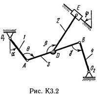
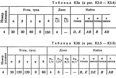
The planar mechanism consists of rods 1, 2, 3, 4 and the slider B or E (Fig. K.0 - K3.7) or from the rods 1, 2, 3 and the sliders B and E (Fig. K3.8, K3. 9) connected to each other and to fixed supports O1, O2 by hinges; Point D is in the middle of the rod AB. The lengths of the rods are l1 = 0.4 m, l2 = 1.2 m, l3 = 1.4 m, l4 = 0.6 m, respectively. The position of the mechanism is determined by the angles α, β, γ, φ, θ. The values of these angles and other specified values are given in Table. KZa (for Figure 0-4) or in Table. KZB (for Figure 5-9); while in Table. КЗа ω1 and ω4 are constant quantities. Determine the values indicated in the tables in the columns "Find". Arc arrows in the figures show how the corresponding angles should be plotted during the construction of the mechanism drawing: in the direction of or against the clockwise direction (for example, the angle γ in Figure 8 should be deposited from DB along the clockwise direction, and in Figure 9 - arrows, etc.). Draw a drawing from the rod, the direction of which is determined by the angle α; the slider with guides for greater visibility is represented as in the example of short-circuit (see Fig. The given angular velocity and angular acceleration are assumed to be directed counterclockwise, and the given velocity vB and the acceleration aB are from point B to b (in Fig. 5-9).
The planar mechanism consists of rods 1, 2, 3, 4 and the slider B or E (Fig. K.0 - K3.7) or from the rods 1, 2, 3 and the sliders B and E (Fig. K3.8, K3. 9) connected to each other and to fixed supports O1, O2 by hinges; Point D is in the middle of the rod AB. The lengths of the rods are l1 = 0.4 m, l2 = 1.2 m, l3 = 1.4 m, l4 = 0.6 m, respectively. The position of the mechanism is determined by the angles α, β, γ, φ, θ. The values of these angles and other specified values are given in Table. KZa (for Figure 0-4) or in Table. KZB (for Figure 5-9); while in Table. КЗа ω1 and ω4 are constant quantities. Determine the values indicated in the tables in the columns "Find". Arc arrows in the figures show how the corresponding angles should be plotted during the construction of the mechanism drawing: in the direction of or against the clockwise direction (for example, the angle γ in Figure 8 should be deposited from DB along the clockwise direction, and in Figure 9 - arrows, etc.). Draw a drawing from the rod, the direction of which is determined by the angle α; the slider with guides for greater visibility is represented as in the example of short-circuit (see Fig. The given angular velocity and angular acceleration are assumed to be directed counterclockwise, and the given velocity vB and the acceleration aB are from point B to b (in Fig. 5-9).
No feedback yet