Solution C2-55 (Figure C2.5 condition 5 SM Targ 1989)
Content: s2-55.doc.RAR (30.20 KB)
Uploaded: 22.04.2016
Positive responses: 0
Negative responses: 0
Sold: 4
Refunds: 0
Seller: Михаил_Перович
information about the seller and its items
Loyalty discount! If the total amount of your purchases from the seller more than:
| $1 | the discount is | 1% |
| $5 | the discount is | 2% |
| $10 | the discount is | 3% |
| $20 | the discount is | 5% |
| $50 | the discount is | 7% |
| $100 | the discount is | 10% |
| $200 | the discount is | 15% |
$0.54
Solution C2-55 (Figure C2.5 condition 5 SM Targ 1989)
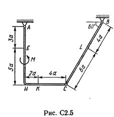
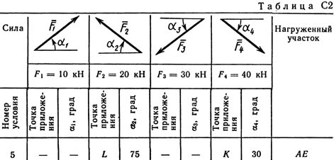
The design consists of a hard corner and a rod, which are either hinged at point C (Figure C2.0-C2.5) or are freely supported against each other (Figure C2.6-C2.9). The external constraints imposed on the structure are at the point A or hinge, or rigid sealing; at point B or a smooth plane (Figures 0 and 1), or a weightless rod BB ´(Figures 2 and 3), or a hinge (Figures 4-9); at point D or the weightless rod DD ´(Figures 0, 3, 8), or the hinged support on the rollers (Figure 7). Each structure is affected by: a pair of forces with a torque M = 60 kN · m, a uniformly distributed intensity load q = 20 kN / m and two more forces. These forces, their directions and points of application are indicated in Table. C2; In the same column in the column "Loaded area" it is indicated where the distributed load is acting (for example, under conditions No.1, the force F2 at an angle of 60 ° to the horizontal axis applied at point L, force F4 at an angle of 30 ° to the horizontal axis , applied at point E, and the load distributed in section CK). Determine the reactions of bonds at points A, B, C (for Figures 0, 3, 7, 8 also at point D), caused by given loads. In the final calculations, take a = 0.2 m.
The design consists of a hard corner and a rod, which are either hinged at point C (Figure C2.0-C2.5) or are freely supported against each other (Figure C2.6-C2.9). The external constraints imposed on the structure are at the point A or hinge, or rigid sealing; at point B or a smooth plane (Figures 0 and 1), or a weightless rod BB ´(Figures 2 and 3), or a hinge (Figures 4-9); at point D or the weightless rod DD ´(Figures 0, 3, 8), or the hinged support on the rollers (Figure 7). Each structure is affected by: a pair of forces with a torque M = 60 kN · m, a uniformly distributed intensity load q = 20 kN / m and two more forces. These forces, their directions and points of application are indicated in Table. C2; In the same column in the column "Loaded area" it is indicated where the distributed load is acting (for example, under conditions No.1, the force F2 at an angle of 60 ° to the horizontal axis applied at point L, force F4 at an angle of 30 ° to the horizontal axis , applied at point E, and the load distributed in section CK). Determine the reactions of bonds at points A, B, C (for Figures 0, 3, 7, 8 also at point D), caused by given loads. In the final calculations, take a = 0.2 m.
No feedback yet